Process
Welcome to Bordentown Sewerage Authority’s Black’s Creek Wastewater Treatment Plant.
This plant represents the consummation of more than fifteen (15) years of local effort aimed at improving the environment of the Bordentown area. Directly benefiting from this effort are the residents of Bordentown Sewerage Authority’s service area which includes the territorial boundaries of both the City and Township of Bordentown. Fully operational early in 1991, the plant has successfully been meeting its discharge permit limits ever since. Our flows are averaging 1.6 million gallons per day and the plant’s rated capacity is 3.0 million gallons per day.

Administration Building
All Bordentown Sewerage Authority activities center around our administration building which house the billing office, conference room, laboratory, various administrative and plant offices and a maintenance shop/garage area.
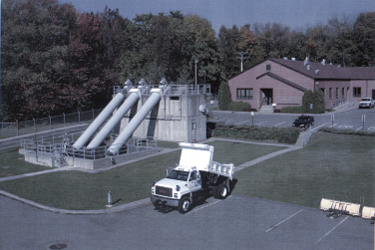
Screw Pump Station
Sewage enters the wet well of the screw pump station, which raises the water high enough to flow via gravity through the rest of the plant.
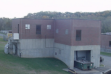
Bar Screen/Grit Building
From there it travels to the Bar Screen/Grit Building. Here, an automatically cleaned bar screen protects the comminutor. A bypass channel is provided for alternate operations. Sewage then flows into an aerated grit chamber that is cleaned with a screw conveyor/bucket elevator/grit washing mechanism and delivered to the dumpster on the outside of the building.
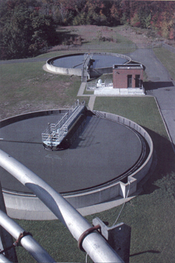
Primary Clarifiers
The flow continues to a splitter box to evenly distribute the flow to two (2) primary clarifiers. Sludge from the one that is in operation at this time is pumped by progressive cavity pumps housed in the primary sludge pump station. Scum collection and pumping is handled here also. Primary sludge and scum are directed to storage tanks in the Sludge Thickening Building.
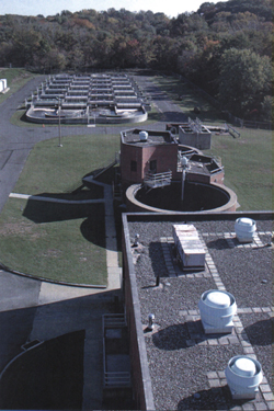
Sludge Thickening Building
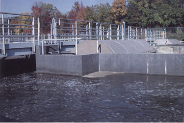
Oxidation Ditch
The plant’s flow travels to the oxidation ditch area where two (2) 1.1 MG volume ditches are aerated with disc aerators.
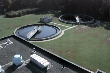
Secondary Clarifiers
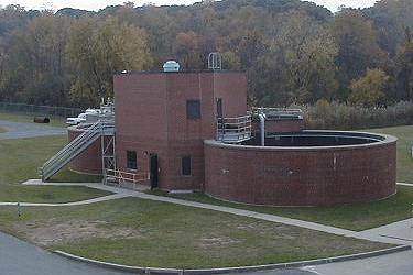
Sludge Thickening Building
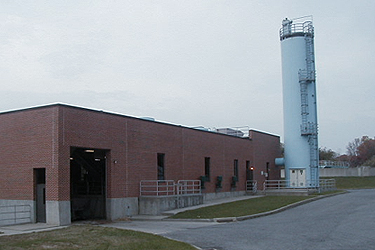
Soda Ash Silo
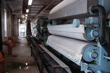
Belt Press Units
Secondary clarifiers settle the activated sludge for return to the ditches via return pumps in the basement of the Sludge/Chemical Building. Sludge wasting pumps located there also deliver to storage tanks in the Sludge Thickening Building. Sieve drum concentrators there thicken sludge before being sent to the liquid sludge loading station located at the far end of the Sludge/Chemical Building or to our belt presses where a sludge cake is produced which in turn is sent to the Burlington County Composting Facility.
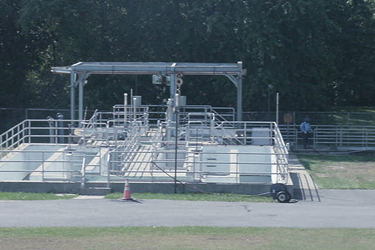
Chlorine Contact Tank
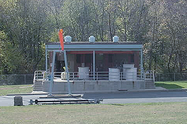
Chlorine Generator Building
Wastewater then proceeds to the chlorine contact tanks for disinfection with the chlorine being supplied by onsite chlorine generation and sodium hypochlorite. Dechlorination takes place in the next tank, using sulfur dioxide being supplied in ton containers. After dechlorination, post aeration tanks are available to provide sufficient dissolved oxygen in the effluent.
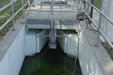
Parshall Flume
Lastly, flow is measured in the Parshall flume and discharged to Black’s Creek.
Electricity supplied by PSE&G is transformered down from 13,200 volts to usable 480 volts in the central power substation, and distributed to the various buildings’ motor control centers. A 1.25 million watt standby generator has been provided for emergency use.
All tanks have drains built into them for dewatering purposes and all drains collect at the central drain pump station for delivery to the head of the plant, thereby eliminating the need for portable pumps for dewatering.
Soda ash, used for alkalinity control, is purchased in bulk and stored in the sixty (60) foot tall silo along side the Sludge/Chemical Building.
